

1. PACK Manufacturing Process Overview
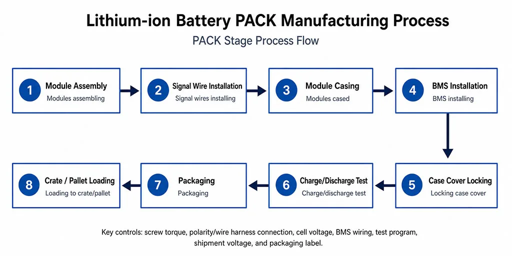
Based on the source PPT, a typical lithium-ion battery PACK process can be divided into eight continuous steps. Each step includes both an assembly action and a quality-control checkpoint.
- Module assembling: group cells, complete series/parallel connections, and fasten the module.
- Signal wires installing: install voltage sampling wires and temperature sensing wires.
- Modules cased: place modules into the enclosure and check polarity, wiring, and voltage.
- BMS installing: install the protection board and connect module wiring, the main circuit, and communication interfaces.
- Locking case cover: secure the enclosure structure for transport and use.
- Charge/discharge test: verify program settings, voltage, capacity, consistency, discharge platform, and temperature rise.
- Packaging: check communication, shipment voltage, accessories, and appearance before sealing the box.
- Loading to crate/pallet: complete wooden-crate or pallet packing and labeling for shipment.
2. Main Process Steps
1. Module Assembling
Module assembly is the starting point of PACK manufacturing. Cells are connected in series and parallel according to the target voltage and capacity, then fixed with connectors to form a stable module. Series connection increases voltage, while parallel connection increases capacity.
- Confirm cell orientation to avoid reverse polarity.
- Check connector position and contact reliability.
- Control screw torque according to the process requirement to avoid looseness or damage caused by over-tightening.


2. Signal Wires Installing
Signal wires are used to monitor the voltage of each cell, while temperature sensing wires monitor the internal temperature of the battery pack. Sampling points must match the BMS acquisition sequence; otherwise, the BMS may read abnormal voltages or make incorrect protection decisions.
- Wire terminals must be fixed securely.
- Sampling wires must not be reversed, inserted incorrectly, or damaged by the enclosure.
- Wire-fastening torque must meet the process requirement.


3. Modules Cased
During module casing, assembled modules are placed into the enclosure. The operator must check wiring routes, terminal positions, module orientation, and internal clearance. After casing, cell voltage and wiring status should be confirmed again.
- Do not confuse positive and negative terminals.
- Do not reverse-plug the signal wires.
- Confirm that voltage meets the process requirement.


4. BMS Installing
The BMS is the management and protection core of the battery pack. It handles voltage acquisition, temperature monitoring, overcharge and over-discharge protection, overcurrent protection, balancing, and communication. During installation, the BMS board, wiring harnesses, and module connections must correspond correctly.
- BMS wiring must not be misplaced.
- Fixing screws must be tightened.
- The main circuit, sampling wires, and communication interfaces must be checked one by one.


5. Locking Case Cover
After internal components are installed, the case cover is locked to secure the enclosure. This step affects not only appearance but also structural reliability during transport, vibration, and long-term use.
- No cover screw should be missed.
- Screws must not be loose.
- After tightening, confirm that the cover fits the case evenly.


6. Charge/Discharge Test
The charge/discharge test simulates customer use and verifies whether the battery pack program, voltage, capacity, consistency, discharge platform, constant-current ratio, and temperature performance meet requirements. Test parameters must follow the process document or customer agreement.
- Confirm product connection and communication status before testing.
- Record voltage, current, capacity, and protection points during testing.
- After testing, judge whether capacity and protection voltage meet shipment requirements.
Charge and Discharge Test Parameter Table
The following table is rebuilt from the PPT screenshot as real HTML table content for publishing, copying, and search indexing.
| Charging and discharging test parameter settings (recording time: 1 s): lower voltage limit 35 V, upper current limit 15 A | ||||||
|---|---|---|---|---|---|---|
| Operation number | Operation Type | Time | Voltage (V) | Current (mA) | Cut-off current (mA) | Notes |
| 1 | Shelved | 0.2 min | Check voltage range: 52.5–58.4 V | |||
| 2 | Constant-current charging | 57 | 50000 | If charging is abnormal, proceed to Step 7; | ||
| 3 | Constant-voltage charging | 57 | 1000 | After discharging for 1 minute, proceed to Step 3. | ||
| 4 | Shelved | 0.2 min | ||||
| 5 | Constant-current charging | 61 | 5000 | Post-charge protection voltage: 59–60.5 | ||
| 6 | Shelved | 0.2 min | ||||
| 7 | Constant-current discharge | 36 | 50000 | Post-charge cut-off voltage: 42.5–44.5; capacity greater than 50 Ah | ||
| 8 | Shelved | 0.2 min | ||||
| 9 | Constant-current, constant-voltage charging | 35 min | 57 | 50000 | 1000 | |
| 10 | Completed | |||||
Note: Summarise the capacity by probability, and the charge/discharge protection voltages. Include information on the charging current for the final process step. Products with a capacity greater than 50 Ah are deemed to meet specifications. Those with a capacity below 50 Ah should be analysed separately. The dispatch voltage is 52.65; affix the corresponding barcode.


7. Packaging
After testing is passed and the product is signed OK, it enters the packaging stage. Before packaging, communication function, shipment voltage, accessory completeness, and appearance must be checked.
- Check whether communication works normally.
- Confirm that shipment voltage meets the requirement.
- Check accessories to prevent omissions.
- Avoid impact during handling and sealing.


8. Loading to Crate/Pallet
The final step is to load products into a wooden crate or onto a pallet for shipment. Operators need to check package labels, product model, quantity, and transport method according to the process document.
- Check packaging labels according to the process document.
- Confirm that the wooden crate or pallet is fixed securely.
- Meet transport requirements for shock prevention, moisture protection, and general protection.


3. Key Quality Control Points
PACK manufacturing is not only an assembly process. It is a system integration process involving electrical connection, structural fastening, protection management, and test verification. Based on the PPT, the key control points are:
- Screw torque: module, wiring, BMS, and cover torque must meet process requirements.
- Polarity and wiring: positive and negative terminals must not be reversed, and sampling wires must not be misplaced.
- Cell voltage: voltage range should be confirmed before casing and testing.
- BMS wiring: the protection board, sampling wires, main circuit, and communication interfaces must be connected correctly.
- Test program: charge/discharge parameters, protection voltage, and capacity judgment must follow the document.
- Shipment status: shipment voltage, accessories, labels, and packaging protection must be confirmed.
4. Conclusion
The lithium-ion battery PACK manufacturing process starts with module assembly and continues through signal wire installation, module casing, BMS installation, case-cover locking, charge/discharge testing, packaging, and final crate or pallet loading. Each process node requires matching quality control, especially for torque, polarity, wiring, BMS connection, test program, and shipment labeling. Only when these details are controlled consistently can the battery pack deliver reliable performance and safety in real-world applications.


